SPECIAL ENGINEERING DESIGN PROJECTS
This is a true consulting service that RGB Engineering can provide to any customer that has a need to investigate or develop a new feature, modification, improvement, or alteration to an existing roll grinder. Most of the machine tool builders and suppliers of new roll grinders prefer large projects, and do not have the time, resources, or inclination to address the needs of the roll shops who may simply want to redesign an existing machine to meet a specific objective. These are usually "one-of-a-kind" projects, and consequently there is very little opportunity to recoup a return on investment for the OEM companies. This is not the case for RGB Engineering - no job is too small or too unique to be considered. Another advantage is that we will tailor a design around a customer's requirements - i.e.: a control vender, certain hardware specifications, software routines, etc. Most larger companies will insist on designing around their own control hardware or other rigid specifications due to standardization issues. Also, often times the customer prefers to maintain control over a portion of a project, like the electrical design. RGB is very flexible in this regard, and will interface with the customer's electrical engineers, or other departments, in the interest of maintaining project objectives.
Feasibility Studies
One specific example of a design project popular with roll shop managers and engineers has been the "feasibility study". This allows verification (or early dismissal) of a concept or idea before a commitment to major funding is made. Some examples of feasibility studies conducted by RGB Engineering are:
|
Hydrostatic Bearing Conversion on Extra Duty Two Wheel Roll Grinder. | |
|
Swing Caliper Installation on 60" Chock Grinder. | |
|
Relocation of Swing Caliper on 80" Grinder. | |
|
Coarse Infeed Retrofit using Subbase Infeed Ball Screw. | |
|
Bed Compatibility Investigation for Grinder Relocation on Old Foundation. |
A few examples of some special design projects completed by RGB engineering are listed below.
Wheel Probe Retrofit
The
Farrel automated roll grinders included a wheel probe, to monitor wheel diameter
for automatic wheel approach, diameter decrease, and to maintain constant
peripheral speeds. Some wheelheads on conventional manual grinders were
machined with a cutout behind the wheelguard for the addition of a future probe.
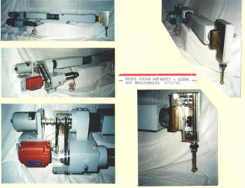 RGB
Engineering has retrofitted a modern probe design onto one such machine, used in
an aluminum mill roll shop. For this particular installation, the customer
provided the probe sequence control logic, and RGB supplied the mechanical and
electrical probe hardware. See the collage of photos on the left for
pictures of the probe assembly. Some of the design features include:
RGB
Engineering has retrofitted a modern probe design onto one such machine, used in
an aluminum mill roll shop. For this particular installation, the customer
provided the probe sequence control logic, and RGB supplied the mechanical and
electrical probe hardware. See the collage of photos on the left for
pictures of the probe assembly. Some of the design features include:
|
Probe head LVDT transducer as opposed to older style limit switches. This has the advantage of an analog output which can be used to provide continuous position feedback, a better defined and more repeatable null point, monitoring of stock removal, monitoring of wheel size, capability to perform the initial alignment function, and a more flexible sequence control. | |
|
Smaller size than conventional Farrel design. | |
|
Scrap wheel size to hub flange diameter of 22-1/2". | |
|
Simplified drive arrangement which utilizes a dc servo and harmonic drive reducer with a timing belt connection to a ball screw actuator. This combination is essentially backlash free. The same Farrel ball spline is used to maintain interchangeability. | |
|
An absolute encoder which interfaces with a PLC for sequence control and limit switch functions. | |
|
Probe head includes integral dehydrator plug for moisture control. |
Two Wheel Roll Grinder Bed Extension
Most Farrel two wheel roll grinders were designed as a "two-piece" bed for machines longer than 352" face length. The main bed and extension were machined at the joint interface to allow for a bolted connection, which resulted in an integral setup after final installation and leveling in the field. Machines 352" and shorter, however, were designed without any provisions for adding a bed extension. These single piece beds had cast end sections with recessed screw barrels and way projections that made it difficult to interface with the normal bed extension.
RGB Engineering was approached by a customer who had purchased a used 232" Farrel two wheel roll grinder, and wanted to increase its length 18' in order to grind a 450" face roll. The engineering work was done in two phases - a preliminary engineering study and proposal phase, and the final detail engineering phase, which included calculations, part drawings, bill of materials, documentation, etc. This was a unique project, as bed lengthening such as this had never been done before. It presented a number of distinctive challenges:
|
Establishing convenient methods for bolting the beds, since the cast end sections did not provide flanges or core openings for accessing the bolts. | |
|
Providing continuous support for the traverse screw. | |
|
Maintaining integrity of the oil reservoirs and lubrication pockets. | |
|
Providing a continuous support surface for the neckrest stands. | |
|
Maintaining the pitch and slope of the coolant trough. | |
|
The method of lengthening the traverse screw. | |
|
Procedures for aligning and leveling the beds. | |
|
Increasing the length of all machine "variables" - Sandvik belts, way covers, service carriers, crown racks, oil plates, screw gib plates, etc. | |
|
New foundation drawing, including calculation of inertia block variables, spring constants, etc. | |
|
Detail drawings of the bed casting, for compatibility of the existing bed and carriage, since there were no planing gages or fixtures. |
The complete engineering package was provided by RGB Engineering, with the customer subcontracting the machining, casting, and installation work locally. The result was a very successful and cost effective installation, allowing grinding of paper mill rolls to the tolerances consistent with the Farrel TWRG accuracies. The machine has been in service since 1989.
Development of Standard Crown Charts
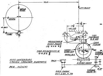
In
addition to manufacturing complete computerized crowner retrofit systems, RGB
Engineering can also supply conventional crown charts for any grinder with a
mechanical "cam" type crowning device. Usually these are machines that
utilize an adjustable eccentric
cam with "change gears" incorporated into the drive train. Although the
OEM should have provided these crown charts, quite ofte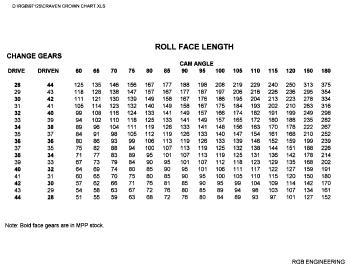 n they were incomplete,
lacking critical data, or may simply have been lost. The example shown
here is for an old Craven roll grinder. Since Craven is no longer in
business, the customer contracted RGB Engineering to develop
a full set of crown charts for this machine. As can be seen from the schematic,
this particular design, which is unique to Craven, includes an adjustable "index
rod" as part of the wheelhead pivot mechanism. The variable distance "x"
has to be factored into the crown
n they were incomplete,
lacking critical data, or may simply have been lost. The example shown
here is for an old Craven roll grinder. Since Craven is no longer in
business, the customer contracted RGB Engineering to develop
a full set of crown charts for this machine. As can be seen from the schematic,
this particular design, which is unique to Craven, includes an adjustable "index
rod" as part of the wheelhead pivot mechanism. The variable distance "x"
has to be factored into the crown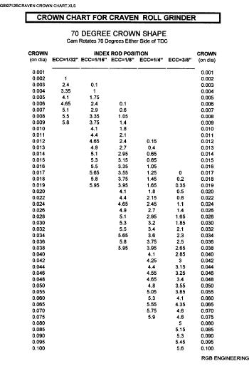 calculations. The middle chart shows the
change gear selection table, and the bottom one is the chart for a 70 degree
profile, with crowns tabulated up to .100". For this application, charts
were supplied for crown shapes of 60 degrees through 120 degrees in 5 degree
increments. The range and increment of both shape angle and crown amount
can be contracted or expanded to suit the customer's requirements. If
requested, the complete Excel spreadsheet documentation can be supplied.
calculations. The middle chart shows the
change gear selection table, and the bottom one is the chart for a 70 degree
profile, with crowns tabulated up to .100". For this application, charts
were supplied for crown shapes of 60 degrees through 120 degrees in 5 degree
increments. The range and increment of both shape angle and crown amount
can be contracted or expanded to suit the customer's requirements. If
requested, the complete Excel spreadsheet documentation can be supplied.
Taper Carriage Project
A roll shop, specializing in manufacturing new rolls as well as regrinding rolls for the paper industry, was planning to relocate to a new facility. Being a full service shop, grinding accurate tapers on the roll journals and necks was a necessity. Due to the relocation and the age of the existing equipment, the grinder that had been dedicated to this function would not be included in the move. Therefore, a method for grinding roll journal tapers had to be devised. RGB Engineering was contracted to solve the problem.
Man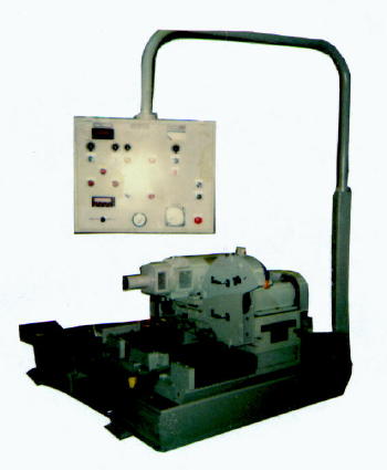 y
alternatives were investigated, but the ultimate solution was to design a
special independent taper carriage, that runs on the same back bed ways.
This carriage does not have its own drive, but is pulled/pushed into position by
the main grinder carriage. It is stored on the tailstock end of the back
bed when not in use, and can be easily removed when required to grind a very
long roll. The photo shows the assembled carriage unit prior to mounting on the
grinder. Of course, what makes this concept feasible is that the grinder
has a long bed (34' O.A.L. roll capacity). Some of the important features
of the taper carriage design concept are as follows:
y
alternatives were investigated, but the ultimate solution was to design a
special independent taper carriage, that runs on the same back bed ways.
This carriage does not have its own drive, but is pulled/pushed into position by
the main grinder carriage. It is stored on the tailstock end of the back
bed when not in use, and can be easily removed when required to grind a very
long roll. The photo shows the assembled carriage unit prior to mounting on the
grinder. Of course, what makes this concept feasible is that the grinder
has a long bed (34' O.A.L. roll capacity). Some of the important features
of the taper carriage design concept are as follows:
|
Since there was minimal interfacing with the main carriage, and since most of the manufacturing and assembly of the taper carriage was done in a remote facility away from the roll shop, there was very little interruption of the production schedule until the final installation. |
|
Since the carriage fits the standard Farrel back bed geometry, it can be moved to other grinders (or sold) in the future should this be a requirement. |
Some of the elements of the design are:
|
The auxiliary taper carriage assembly consists of:
|
|
Only the tailstock end journal can be ground. The roll has to be turned end-for-end to do both journals. |
|
The operator runs the taper carriage from the front side of the grinder, using an easily accessible pendant control panel. The advantage of the front operation is that it simplifies the design, since the carriage does not have to accommodate an operator. | |
|
The upper carriage rotates on a bearing pivot appropriately positioned to optimize the geometric relationships. Air bearings lift and support the upper carriage during the taper adjustment. A vernier scale assures accurate settings. Manual clamps secure the top carriage to the base after the adjustment is made. | |
|
The design philosophy is to utilize standard components wherever possible - i.e.: the spindle assembly, infeed cross slide, longitudinal slide ways, etc., are all commercial components, as well many other parts. | |
|
The wheel and carriage are powered by variable speed drives for maximum operator control. Wheel infeed is controlled via an electronic handwheel. An ammeter and other miscellaneous gages and readouts are located on the pendant. | |
|
Sufficient slack is provided in the electrical, hydraulic, and coolant lines to allow the complete carriage to be lifted off the bed, rotated, and stored adjacent to the back bed, should it be necessary to run the main carriage the complete length of the bed when grinding a long face length roll. Lifting brackets are provided to simplify the removal and reinstallation. |
The
taper carriage has been in service since 1991, allowing this customer to grind
flat and tapered jour nals on a variety of different types and sizes of rolls to
the quality standards required by the paper industry. The picture on the
right, taken in 2002, shows the taper carriage in its stored position on the
bed.
nals on a variety of different types and sizes of rolls to
the quality standards required by the paper industry. The picture on the
right, taken in 2002, shows the taper carriage in its stored position on the
bed.
Craven Traverse Handwheel
Problems were experienced with the traverse mechanism on an old Craven roll grinder, that is being used for side-face grinding as well as OD grinding in a specialized roll shop. Due to wear of the internal gear train elements, the existing carriage handwheel operation had become erratic and unpredictable, resulting in excessive plunging of the cut during a side-face grinding sequence, and extra production time to repair the damage. Although it might have been possible to repair the existing mechanical transmission, it was decided that the best approach was to bypass this gear cluster completely, using an external timing belt drive to an extension shaft bolted to the output shaft pulley hub. The advantage of the independent drive option was that the machine could still be used for normal grinding functions while the new parts were being designed and manufactured. Also, there was no guarantee that the worm parts would be available, since Craven is no longer in business.
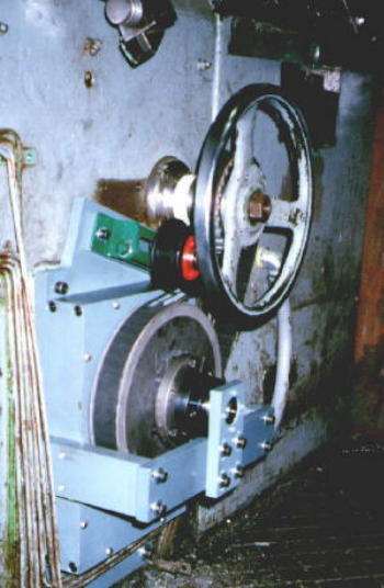
The picture shows the final drive arrangement after the conversion. An electric clutch is used to disable the handwheel whenever the traverse drive is being run under motorized control. Conversely, the motor is interlocked so that it can not run when in the handwheel mode. Since the elements of the gear train that were causing the erratic handwheel operation are "upstream" of the driven pulley, the motion with the new drive arrangement is smooth, and the customer is able to perform side face grinding with increased accuracy and reliability.
Landis Grinder Chock Supports
RGB Engineering designed special chock supports and a roll drive arrangement to allow the grinding of 140" plate mill work rolls in a 36" Landis grinder without stripping the chocks. The chocks are supported in the stands at a slight angle resting on the liners. The side reaction is through a motorized pusher for adjusting the chocks in and out to establish roll alignment.
Since the Landis 36" grinder's swing diameter over the front bed was not sufficient to allow the 39-1/4" diameter roll to be supported on the headstock centerline with the chocks in place, a universal drive bar is employed to permit grinding the roll 10" above the wheel centerline. Adapters are used at each end of the universal to engage the headstock faceplate and the roll flats.
This conversion was made in 1988, and has been an important part of the customer's commitment toward producing quality roll grinding at reduced operating costs using the technique of grinding rolls "in chocks".
Farrel Subbase Infeed Retrofit
Virtually all Farrel tilt infeed single wheel roll grinders manufactured after 1959 included a two speed subbase infeed drive. This was accomplished using two separate AC motors with a clutch mechanism to rapid feed the subbase in or out @ 28 ipm, and to feed the subbase in at a slow speed (2 ipm) when approaching the work. Due to problems with the clutch, brake, and plugging switch hardware, this has been a maintenance issue on many machines. Farrel redesigned the drive arrangement on later machines to utilize a single DC variable speed motor, eliminating the clutch. this required a new motor, drive, motor mounting bracket, and sometimes a new worm shaft.
RGB Engineering has supplied retrofit packages on the earlier style grinders with the two motor design, using a variable speed AC drive to interface with the same AC high speed motor. The advantage is that the existing motor can be used, and no mechanical alterations have to be done to the machine. This is a much more cost effective and simpler solution to the problem.
Turning Tool Attachment
An aluminum mill roll shop contracted RGB Engineering to modify their 60" Farrel grinder to supplement the normal grinding function with a wheelhead mounted lathe tool to "turn" continuous caster work rolls. This involved a comprehensive engineering study, expanding on work that had been done at Farrel in the seventies and eighties, to retrofit the standard wheelhead to accept the lathe tool components and associated controls and hardware.
The turning operation is done with the roll mounted in the standard neckrest supports and on the same journal surfaces that are used to support the roll during the normal roll grinding. This is an important point, because, unlike the roll that is turned in a conventional engine lathe on centers, the setup on neckrests assures that the roll body will be concentric to the necks after the turning is finished. Usually, only a few grinding passes are necessary to clean up the roll surface after turning.
The same headstock and equalizer drive are used to rotate the roll as with grinding. The roll rotation is the same - counterclockwise looking at the headstock faceplate. The headstock motor horsepower, as well as the torque capacity of the V-belt drive is normally sufficient to handle the extra torque requirement from the turning forces. This is because the headstock and motor are usually designed with an ample safety factor to account for the increased torque required to start a roll on dry necks. Since the turning forces are applied only after the roll is running under the lower friction condition, this residual or reserve torque is available for this purpose. RGB Engineering has developed a specialized computer program to analyze the forces and torques for a given motor size, headstock capacity, and roll geometry.
The
wheelhead front face was machined to accept the tool holder assembly, the
mountin g of which is depicted in the diagram on the left. There are no
other mechanical modifications required to the wheelhead, subbase, or carriage,
other than the addition of a small coolant nozzle for the cutting tool.
One of the advantages of the wheelhead mounted cutting tool, as opposed to a
front bed independent carriage or even a standard engine lathe, is that the
crowning mechanism can be engaged while turning to produce crown or concave
profiles, the same as if grinding.
g of which is depicted in the diagram on the left. There are no
other mechanical modifications required to the wheelhead, subbase, or carriage,
other than the addition of a small coolant nozzle for the cutting tool.
One of the advantages of the wheelhead mounted cutting tool, as opposed to a
front bed independent carriage or even a standard engine lathe, is that the
crowning mechanism can be engaged while turning to produce crown or concave
profiles, the same as if grinding.
Another
distinct difference between conventional turning and the setup on the roll
grinder is the tool geometry. A "broadnosing" technique is used to peal
stock off the sleeved caster roll. Broadnosing exposes the flat edge of the tool
to the work, as opposed to the tool tip as with normal single-point turning.
With broa dnosing, the depth of cut is less, but the feed rates are higher. The
procedure for
turning a roll is not unlike that for grinding. The tool infeed is accomplished
using the tilt infeed handwheel, and the graduated index dial, for setting
accurate feed increments. The carriage and headstock speeds fall into the
normal roll grinder operating ranges, which is the primary reason broadnosing is
used. The photo shows a roll being turned. Note the formation of the
chip, and the exceptionally clean finish cut.
dnosing, the depth of cut is less, but the feed rates are higher. The
procedure for
turning a roll is not unlike that for grinding. The tool infeed is accomplished
using the tilt infeed handwheel, and the graduated index dial, for setting
accurate feed increments. The carriage and headstock speeds fall into the
normal roll grinder operating ranges, which is the primary reason broadnosing is
used. The photo shows a roll being turned. Note the formation of the
chip, and the exceptionally clean finish cut.
Special Supports for TTRG
RGB Engineering was contracted to design a special set of roll supports for a unique style traveling table roll grinder installed at a steel mill in the PRC. The requirement was to grind small diameter leveler rolls in a grinder designed for much larger work. Specifically, the grinder has a 711 mm diameter roll capacity, but the Chinese wanted to grind rolls less than 95 mm diameter, with a 25 mm diameter journal. This required an innovated concept for the steady rests and roll drive equipment.
The existing neckrests were replaced with a support stand, bolted together by tie rails at the bottom, and the way structures at the top. Each main support has provisions for clamping to the table using the same clamping surface used for the neckrests. Bolted to the top of the main supports are a set of stainless steel rectangular ways, fastened so that the bottom and side gib blocks can slide the complete length of the ways, and can be removed from each end if necessary. This permits additional gib blocks to be used as required by the number of support points on the particular leveler roll being ground. The gibs are infinitely adjustable along the ways, so that they can be lined up with specific support areas, and as many or as few can be used as dictated by the roll to be ground.
Hand adjusted clamp screws, accessible from the operator's side of the machine, are used to lock the gib blocks in place on the rails. Also, each gib block includes a movable gib with the same kind of hand adjustment for positioning the gibs at the correct radius. Teflon type material is used for the gib contact elements so that coolant water can be used for lubrication.
The a ttached
portion of the design layout drawing is included to give some perspective of the
sizes involved. A complete engineering package (detail drawings, assembly
drawing, bill of material listing, commercial component selection, etc.) was
supplied in metric standards for manufacturing in China.
ttached
portion of the design layout drawing is included to give some perspective of the
sizes involved. A complete engineering package (detail drawings, assembly
drawing, bill of material listing, commercial component selection, etc.) was
supplied in metric standards for manufacturing in China.
Hydrostatic Steadyrest
RGB Engineering provided a complete design engineering package for a set of hydrostatic steadyrests, as part of the overall design of a large backup roll grinder manufactured by a leading supplied of new roll grinders. The requirement for this aluminum mill application included the support and grinding of a 184,000 pound backup roll with 37" diameter journals. Due to the roll weight and large diameter necks, the torque capacity of the headstock was inadequate to start the roll. Rather than complicate the headstock design with a starting motor, or unnecessarily inflate the cost with a beefed up design, the solution to the problem was the hydrostatic gib. Actually, it should be called a hybrid hydrostatic design, since the primary function of the hydrostatic bearing is for "load relieving" during the starting sequence of the roll. The gib has two pressure pockets. A central high pressure recess for starting, and a an outside peripheral groove for low pressure oil feed during grinding. Once the roll is rotating, the bearing functions more in a hydrodynamic mode, supplying oil as required to maintain proper boundary lubrication during the grinding operation.
RGB
Engineering supplied the design for the complete neckrest assembly, but the
inimitab le
feature is the "double-radiused" bottom gib. The basic design principles
are shown in the attached portion of the cross-section drawing.
Essentially, what makes this unique is the inherent self-aligning quality of the
bearing. The support elements are made in two pieces. A bearing shoe
has an inside radius to match the journal, and an outside contour of smaller
radius. This bearing is supported in a bottom gib holder, radiused to
match the shoe, and designed to mate with the bottom gib wedge in the
conventional manner. A static analysis of the force vectors, for both the
starting condition as well as when running, verify the self-aligning features of
the bearing. The radiused slide surfaces are manufactured with Rulon
liners to minimize friction, and promote the self adjusting action. The
actual bearing material is Babbitt, with integral O-rings to help maintain
pressure during the load relieving cycle.
le
feature is the "double-radiused" bottom gib. The basic design principles
are shown in the attached portion of the cross-section drawing.
Essentially, what makes this unique is the inherent self-aligning quality of the
bearing. The support elements are made in two pieces. A bearing shoe
has an inside radius to match the journal, and an outside contour of smaller
radius. This bearing is supported in a bottom gib holder, radiused to
match the shoe, and designed to mate with the bottom gib wedge in the
conventional manner. A static analysis of the force vectors, for both the
starting condition as well as when running, verify the self-aligning features of
the bearing. The radiused slide surfaces are manufactured with Rulon
liners to minimize friction, and promote the self adjusting action. The
actual bearing material is Babbitt, with integral O-rings to help maintain
pressure during the load relieving cycle.
Hydrostatic bearings are commonly used in machine tool spindles, or other applications that have consistent and accurate dimensions functioning in a relatively clean environment. What makes this application unique, is that the bearing has to operate against a roll journal with mill quality standards in an open roll shop environment. The design as briefly described above, together with a suitably designed hydraulic control system, has functioned well under adverse operating conditions.