INSTALLATION EXAMPLES: LANDIS TRAVELING CARRIAGE ROLL GRINDER
COMPUTERIZED CROWNER RETROFIT SYSTEM
The
standard older style Landis Type 30 traveling carriage roll grinder includes a
mechanical cam type crowning device for grinding sinusoidal shapes on the roll
bodies. The crown cam is driven via a ta ke-off
shaft from the traverse g
ke-off
shaft from the traverse g earbox,
through a change gear interface as shown in the photo at the right. The
output or "driven" change gear connects to the cam actuator assembly (shown on
the left) by means of a horizontal crossover shaft passing under the carriage
step. A right angle anti-backlash double worm unit meshes with the worm
gear that is integral with the cam shaft assembly. Therefore, as the
carriage traverses along the bed, the cam rotates. The "cam" is really not
a cam in the true sense, but rather an eccentric which is offset a specific
amount from the true center of rotation. A cam follower vertical slide
member imparts this crowning motion to the grinding wheel through the tilting
subbase cambering system. This consists of a simple trunnion pivot
arrangement, with support points at the two front pivots, and the center mounted
lever arm extending out the rear over the cam follower lift point.
Mechanical superposition of the crown input with the normal handwheel slide
infeed is achieved with this system. The normal wheel infeed occurs
between the camber base (subbase) and the upper slide member (wheelslide).
For this vintage Landis design, compression springs mounted between the carriage
and the tilting subbase relieve a portion of the load on the cam. For this
particular retrofit application, which was part of a total
earbox,
through a change gear interface as shown in the photo at the right. The
output or "driven" change gear connects to the cam actuator assembly (shown on
the left) by means of a horizontal crossover shaft passing under the carriage
step. A right angle anti-backlash double worm unit meshes with the worm
gear that is integral with the cam shaft assembly. Therefore, as the
carriage traverses along the bed, the cam rotates. The "cam" is really not
a cam in the true sense, but rather an eccentric which is offset a specific
amount from the true center of rotation. A cam follower vertical slide
member imparts this crowning motion to the grinding wheel through the tilting
subbase cambering system. This consists of a simple trunnion pivot
arrangement, with support points at the two front pivots, and the center mounted
lever arm extending out the rear over the cam follower lift point.
Mechanical superposition of the crown input with the normal handwheel slide
infeed is achieved with this system. The normal wheel infeed occurs
between the camber base (subbase) and the upper slide member (wheelslide).
For this vintage Landis design, compression springs mounted between the carriage
and the tilting subbase relieve a portion of the load on the cam. For this
particular retrofit application, which was part of a total
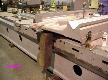 machine rebuild by
Metal Manufacturing Company, since many of the necessary cam drive parts
were missing from the candidate Landis grinder, it was decided to replace
the complete cam mechanism with a new Servo Linear Actuator (SLA). The
photo on the left shows the stripped down carriage and subbase before the
crowner retrofit. One of the compression springs is shown, removed from
its mounting location, for clarity.
machine rebuild by
Metal Manufacturing Company, since many of the necessary cam drive parts
were missing from the candidate Landis grinder, it was decided to replace
the complete cam mechanism with a new Servo Linear Actuator (SLA). The
photo on the left shows the stripped down carriage and subbase before the
crowner retrofit. One of the compression springs is shown, removed from
its mounting location, for clarity.
The
mechanical system as described above has the advantage of simplistic operation,
but is limited to the development of pure sinusoidal crown shapes only.
The FFG/FFP/SLA crowner retrofit addresses this issue, by utilizing a ball screw
actuator for controlling the crown axis in conjunction with the basic elements
of the proven trunnion tilt infeed system (SLA), which engages the subbase at a
point slightly inboard of the old cam follower slide. The ball screw
actuator is designed for positive action due to the constant gravity preload
effect and minimized backlash of the mechanical assembly. This SLA is
combined it with a state of the art computer system (FFG) and customized
software (FFP) for producing any desired roll shape. The DC servo motor
operates through a harmonic drive reducer and timing belt reduction to rotate
the ball screw and actuate the existing subbase. The photos below show the
crowner SLA assembly on the rebuilt Landis grinder after the conversion.
Carriage position is monitored using a multi-turn absolute encoder, coupled to a
spur gear that engages a new rack bolted on the side of the back bed. This
feeds a digital display output on the computer as well as producing the signals
for the “x” axis of the crown profile.
With this setup, the wheel infeed can be controlled very accurately with the
servo motor. There are no adjus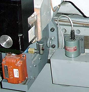 tments require
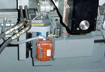 d as there were with the
mechanical cam system. Wheel “infeed” and “outfeed” is determined by the
direction of motor rotation. This has the additional advantage of always
maintaining a positive gravity preload, since the cam never goes through TDC
where the reaction forces change direction.
d as there were with the
mechanical cam system. Wheel “infeed” and “outfeed” is determined by the
direction of motor rotation. This has the additional advantage of always
maintaining a positive gravity preload, since the cam never goes through TDC
where the reaction forces change direction.
The command signals are produced by the FFG, which is located in a floor mounted
enclosure. An IBM compatible industrially rated computer, serially
connected to the PLC, interfaces through an A/D board and other peripheral
devices to provide the outputs to the SLA. The FFG receives 16 bit digital
inputs from the absolute encoder, and produces digital profiles from the FFP
software. The outputs go through a 15 bit D/A, then into analog summing
circuits to command the servo motor for y-axis positioning.
To minimize backlash and lost motion, a LVDT is mounted on the back of the
subbase to measure the crowning action directly, taking into account the
magnification effect due to the pivot ratio. This then forms the linear
feedback to complete the positioning servo loop.
In addition to the normal functions of computerized crowning, bed correction,
and the automatic trip switch feature, this order also includes the precision
infeed and handwheel options.