LASER ALIGNMENT SYSTEM
Quite
simply, this product will enhance roll setup technology by improving antiquated
methods for establishing, checking, and maintaining alignment of the roll
centerline to the headstock center of rotation on virtually any roll grinder.
Implementing this gaging system concept should improve the grinding accuracy,
since it will be much easier for the operators to check and correct the roll
alignment than is normally the case. In addition, chatter and pattern
problems will be encounter less frequently, which quite often are the result of
a severe misalignment between the roll centerline and the true center of
rotation.
Background
This has been an area of concern when troubleshooting grinding problems for a
number of years now. Many vibration and machine inspection reports include
references to the headstock roll driver once or twice per revolution knock.
This causes a heavy thump that transfers throughout the machine, and can
precipitate chatter and pattern conditions, as well as the “flash” problem
sometimes seen on rolls ground eccentric to the headstock driver. The
photo on the right, taken during an inspection of a typical Farrel grinder, shows
the results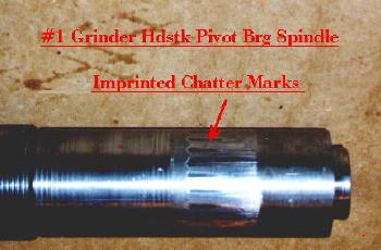 of severe misalignment on the pivot bearing shaft. Note the
evidence of “chatter” marks around the circumference, which were obviously
caused by an extreme condition, resulting in excessive movement of the pivot
mechanism, and abnormally high stresses on the supporting elements.
of severe misalignment on the pivot bearing shaft. Note the
evidence of “chatter” marks around the circumference, which were obviously
caused by an extreme condition, resulting in excessive movement of the pivot
mechanism, and abnormally high stresses on the supporting elements.
With regard to roll centering, it is important to recognize the differences
between “roll grinding”, as opposed to a conventional cylindrical grinder or
lathe type application. These machines generally support the roll on live
or dead centers, with steady rests used as auxiliary support only, so the roll
is always on true center. This is not the case with a roll grinder, which
utilizes Babbitt lined gib blocks for support of the roll on the journals only.
Since the Babbitt is continuously wearing, the roll centerline is constantly
dropping. In addition, wear of the side gibs results in operator
adjustments to maintain taper tolerance, which generally moves the roll
centerline toward the wheel (due to backlash in the adjusting screw, the
adjustment is usually made in this direction). The net result of the
bottom and side gib Babbitt wear is an increasing offset between the roll
centerline and the true headstock center of rotation. The severity of the
problem is a function of the number of rolls ground, headstock speed, grinding
loads, journal lubrication, Babbitt specs, etc.
Typically, the Farrel headstock equalizer is designed to compensate for not more
than .100” of misalignment; however, offsets significantly less than this can
have detrimental effects on roll geometry and finish. Therefore, it is in
the best interest to institute a program that will insure roll misalignment
never exceeds acceptable limits.
Conventional Methods of Control
Generally, there are two methods used to center the rolls to the headstock
rotation.
1. The more common approach is to retract the neckrest bottom and side gibs,
mount the roll on the headstock and tailstock centers, and then readjust all the
gibs with the roll supported on the dead centers.
2. Another method is to use a long stem dial indicator mounted on the headstock
faceplate readin g
against the roll neck. The headstock is rotated slowly (the drive collar
can be left on if there is a keyway in the journal), and the TIR is measured in
the vertical and horizontal planes. The sketch and photo on the right
shows this setup. The headstock end bottom and side gibs are adjusted
until the TIR is close to zero. Then another dial indicator is used to
tram along the top of the roll as the carriage is traversed from one end to the
other, and the tailstock bottom and side gibs are adjusted accordingly.
g
against the roll neck. The headstock is rotated slowly (the drive collar
can be left on if there is a keyway in the journal), and the TIR is measured in
the vertical and horizontal planes. The sketch and photo on the right
shows this setup. The headstock end bottom and side gibs are adjusted
until the TIR is close to zero. Then another dial indicator is used to
tram along the top of the roll as the carriage is traversed from one end to the
other, and the tailstock bottom and side gibs are adjusted accordingly.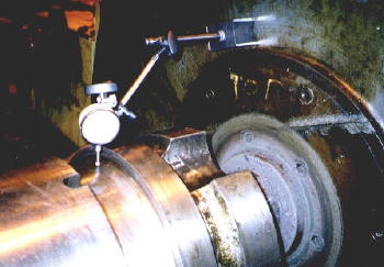
There are a number of problems with method #1:
a) The roll centers are usually not machined concentric to the roll journals; in
addition, they are often worn, pitted, and sometimes badly abused.
b) If the thrust force is not adequate, the weight of the roll makes it
difficult to achieve a good fit in the centers, causing the roll to drop below
center. This can be a real problem with backup rolls in the larger
grinders.
c) The angle of the centers does not always match the angle of the center hole
in the roll.
d) The tailstock traverse and quill feed may not be operative. Some
grinders have a motorized traverse and quill; some only have manual handwheels.
Usually, the tailstock is not used that often, resulting in binding of the
mechanical mechanisms or electrical problems due to lack of use.
e) Sometimes the center points are missing, lost, or damaged.
f) Probably the biggest obstacle to putting the roll on centers is that it
requires a major physical effort and time expenditure on the part of grinder
operator, as well as occupying overhead crane time. Consequently, they usually
find a way to avoid this exercise, and will opt to let the grinder run as long
as it can in the misaligned condition.
It is also difficult to get the operators to use the dial indicators to check
and correct roll alignment. The reasons are as follows:
a) They need a long travel indicator with a good magnetic base and a long enough
arm to reach the roll neck. These are usually not readily available.
b) It is difficult to watch the indicator movement as it rotates through 180
degrees. An additional person is usually required, or mirrors must be
used.
c) Since the roll centerline is usually below the headstock centerline (due to
the fact that the gib Babbitt has worn), the bottom gib must be raised to bring
the roll back on center. It is very hard to turn the gib adjusting screw
with the weight of the roll on the stands, especially backup rolls.
d) The process is time consuming since a number of dial indicator checks are
required in two planes to get the roll on center.
e) Some of the operators don’t understand the technique, and have trouble
reading and setting the indicators; thus, they are reluctant to attempt to try
to learn the method.
The above notwithstanding, the dial indicator procedure has proven to be an
excellent method to troubleshoot and evaluate the grinder’s alignment condition.
Invariably, when making these random checks in a customer’s roll shop, the rolls
are found to be significantly out of alignment, sometimes as much as 3/8”!
It should be noted that an Eddy current gage only checks for roll “level”, and
cannot measure the absolute position of the roll relative to the headstock
rotation.
Mechanical Roll Alignment Gage
In the past, RGB Engineering has promoted a roll alignment gaging system that
uses fixtures and lightweight disks that register in pads and pockets machined
into the neckrest stands. This concept has been used in some instances,
and still has merit for certain situations. But the laser approach is a
more state of the art solution to the problem, and should be more readily
accepted by the operators.
Proposed Laser Alignment System – General Description
The laser alignment system being offered now has the fundamental advantage of
simplistic operation, which hopefully will encourage the operators to use it on
a regular basis, and maintain good alignment of the roll centerline to the
headstock. The tailstock center is removed, and a laser instrument
permanently mounted inside the cavity. A receiver unit is used to
initially “buck” in the laser by registering in the headstock spindle, and then
on an ongoing basis to set the proper position of the bottom and side gibs using
a ring type fixture. The laser can also be used in a visual mode without
the receiver, by viewing the beam projection directly on the end of the roll, to
get a rough idea of the roll position in the grinder. For more accuracy, a
lightweight template with a target grid is supplied. This can be easily
set on the tailstock end of the roll and the beam projection viewed with respect
to the grid cross-hairs.
There are many advantages of this gaging system compared to current practices:
a) The procedure is straightforward, simple, and easy for the operators to
understand. Thus, they will be more inclined to keep the rolls lined up.
b) Alignment time should be less than methods “1” and “2” previously described.
c) It is not necessary to hang the rolls on centers. Therefore, the
overhead crane will not be required, freeing it up for other functions.
d) The gib adjustments are made without the roll in the machine, so minimal
effort is required to adjust the gibs, and the operators have less physical work
to do.
e) Roll centerline position can be easily checked at any time by anyone just by
turning on the laser beam.
A five sheet drawing is available upon request that describes the complete
assembly: Sheet I shows the mounting arrangement of the laser head in
the tailstock, and sheet 2 shows details of the receiver mounting on the
headstock center. Sheet 3 shows the neckrest receiver setup, and sheet 4 the
targets on the roll ends. Sheet 5 is the parts list. The actual
laser is provided by Pinpoint Laser Systems - details of the Microgage 1000 laser
alignment hardware can be accessed at
www.pinlaser.com.
Listed below are some general comments, specifications, design highlights, etc.,
that describe the complete system in more detail.
Laser Mounting Arrangement
As noted above, the center is removed from the tailstock quill exposing the
Jarno taper bore. The referenced drawing shows a Farrel 50” tailstock assembly, but
it will also fit a 36”. An engineering study would be required to
determine the feasibility for other makes of grinders, but the likelihood is
that similar mounting principles would apply. A tapered mounting ring
registers in the bore at the inboard end, and serves as the fulcrum point for
the gimbaled double pivot assembly. This is simply two needle bearings
arranged at 90 degrees to provide a two degree of freedom support of the bracket
extension at the inboard end of the tapered bore. Since the parts are
machined concentric to the bore, the centerline of both pivots should be on the
true machine centerline at this point.
The laser bolts to the support plate as shown at the proper height with respect
to the aforementioned pivots. Four ¼” tapped holes have to be drilled in
the outboard face of the tailstock spindle, which serve as mounting points for
the fixture ring. An end plate, machined for vertical guide keys, is
adjusted up and down using set screws in the fixture ring. Similarly,
using set screws in the end plate, the laser mounting plate can be adjusted
side-to-side in the horizontal plane. Once alignment is obtained, the
support plate is bolted to the end plate using two ¼” cap screws. There is
an oversize hole in the support plate to allow for horizontal and axial
adjustment variation. Slotted holes are also provided in the rear
connection for axial compensation as well.
An end cover, which fits loosely over the fixture ring, serves as protection for
the laser parts, and als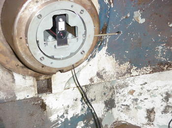 o as a bumper for controlling the roll axial position.
A ball thrust bearing pressed into the end cover serves as the contact point
with the roll. Any thrust forces will be transferred directly through the
end cover to the tailstock spindle.
o as a bumper for controlling the roll axial position.
A ball thrust bearing pressed into the end cover serves as the contact point
with the roll. Any thrust forces will be transferred directly through the
end cover to the tailstock spindle.
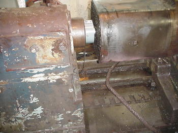
The photo above shows the laser mounting in the tailstock before the end cover
was installed. The photo below shows the actual setup during grinding with
the end cover in place.
Normally, the laser is powered by batteries, but for this application, a
transformer power-pack is included for a 120 volt supply. An On-Off switch
is provided to turn the laser beam on and off. The receiver unit is powered
by a 9 volt battery.
Initial Alignment Procedure
The vertical and horizontal adjustments are made in conjunction with the
receiver unit that is temporarily mounted on the headstock center (see
discussion below). This is a one-time adjustment; once the laser is lined up
true to the headstock center, no further adjustments should be required.
However, it is recommended that periodic checks be made, at least initially, to
verify that alignment is being maintained, especially if the tailstock is moved.
(Installation checks showed that the alignment accuracy was not significantly
affected when the tailstock was moved on the bed approximately six feet.)
Receiver Mounting Arrangement – Headstock Center
The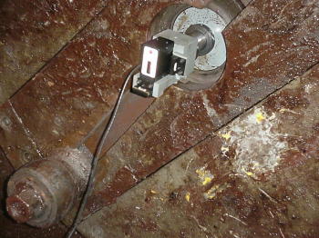 receiver mounts on the headstock center. A precision ground
shaft registers in the headstock spindle tapered bore, and provides a mounting
axis for the receiver bracket concentric to the headstock center of rotation. An
adapter bracket slides on the shaft, and serves as a support plate for the
receiver unit. The photo on the left shows this setup.
receiver mounts on the headstock center. A precision ground
shaft registers in the headstock spindle tapered bore, and provides a mounting
axis for the receiver bracket concentric to the headstock center of rotation. An
adapter bracket slides on the shaft, and serves as a support plate for the
receiver unit. The photo on the left shows this setup.
In the location shown, the receiver will measure the laser beam position in the
vertical plane to an accuracy of about .001”. The attached spirit level is used
to orient the bracket assembly in this position. Then the vertical adjustment
can be made on the laser as described above. When this is done, the receiver
unit is rotated on the shaft exactly ninety degrees. The other spirit level is
used to verify the horizontal orientation, and the horizontal adjustment made on
the laser mount. A check should be made in the vertical plane to verify
alignment.
Receiver Mounting Arrangement – Neckrest
The received can also be mounted on the neckrest gibs. If it is
determined that the roll is significantly off center, then each set of gib
blocks in the neckrest stands should be set on true center. This is done using
the same receiver unit, but mounted in a different fixture.
The neckrest fixture consists of two lightweight aluminum plates, machined to
the exact diameter of the roll necks, fastened together with four tie rods
equally spaced as shown. The receiver unit is bolted to the center tie
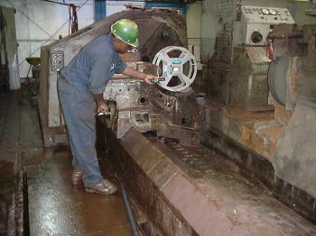 plate.
The fixture is positioned axially in the approximate center of the gibs, and the
spirit level used to orient the round disks in the vertical plane. The bottom
gib is adjusted to bring the readout to zero. The other spirit level is used to
set the fixture at ninety degrees for measuring in the horizontal plane. The
side gib is adjusted to bring the readout to zero. The vertical plane
measurement is repeated, and a final adjustment can be made if required. The
photo above shows the fixture being used on the headstock end neckrest to set up
the gibs. The same procedure is used on the footstock neckrest. For the larger roll neck on the backup roll, three segment sections are
bolted to the base fixture to extend the diameter range. Wing nuts are used to
minimize the changeover time.
plate.
The fixture is positioned axially in the approximate center of the gibs, and the
spirit level used to orient the round disks in the vertical plane. The bottom
gib is adjusted to bring the readout to zero. The other spirit level is used to
set the fixture at ninety degrees for measuring in the horizontal plane. The
side gib is adjusted to bring the readout to zero. The vertical plane
measurement is repeated, and a final adjustment can be made if required. The
photo above shows the fixture being used on the headstock end neckrest to set up
the gibs. The same procedure is used on the footstock neckrest. For the larger roll neck on the backup roll, three segment sections are
bolted to the base fixture to extend the diameter range. Wing nuts are used to
minimize the changeover time.
Quick Alignment Check
A roug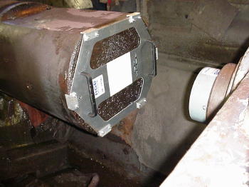 h check on the roll alignment can easily be done by simply turning on the
laser, and observing the red dot directly on the tailstock end of the roll neck. The dot should be concentric to the center countersink. However, contamination
and roll damage may affect the accuracy of this reading. A more accurate check
can be made using target fixtures. These are lightweight aluminum disks designed
to fit over the end of the roll neck, as shown on the above photo. The white targets with concentric circles and crosshairs
(not visible in the picture) make it much easier to tell at a glance the degree
of roll misalignment to within approximately +/- 1/64”.
h check on the roll alignment can easily be done by simply turning on the
laser, and observing the red dot directly on the tailstock end of the roll neck. The dot should be concentric to the center countersink. However, contamination
and roll damage may affect the accuracy of this reading. A more accurate check
can be made using target fixtures. These are lightweight aluminum disks designed
to fit over the end of the roll neck, as shown on the above photo. The white targets with concentric circles and crosshairs
(not visible in the picture) make it much easier to tell at a glance the degree
of roll misalignment to within approximately +/- 1/64”.
Safety
The Microgage uses a class 3A laser, with less than a 5 milliwatt output, and is
safe for the roll shop application. It is widely used in similar industrial
environments. A class 3A warning label will be supplied.
Commercial
An approximate price for one laser alignment system as described designed for a
50” Farrel grinder, complete with the Microgage 1000 standard system as
specified in the catalog with power supply for 120 volt, laser mounting
brackets, end cover, receiver mounting brackets for the headstock center and
neckrest gibs, and journal targets is
$15,000.00
The above price assumes two different roll setups on straight (not tapered) gibs
- i.e.: two different diameter roll necks and end journals. The final price
could be higher or lower depending on how many roll setups are required. This
will be determined either by a site inspection, and/or by a detailed review of
the drawings. Once this is done, a firm fixed price quote can be supplied.
The price does not include field time and expenses by RGB Engineering to assist
with the installation and setup. This could be done by in-house people, but
it is recommended that RGB Engineering be involved if possible. RGB can also supply a field
technician if shop mechanics are not available. This work would be done at the
normal service rates.
There is a one year warranty on the laser equipment provided by Pinpoint Laser
Systems.
Delivery of the complete assembly is about 12 weeks; this could vary depending
on the job complexity and workload at the time of the order.
Terms: Net 30 days, subject to a 1-1/2% per month interest on overdue balance.
Freight: pp & add, FOB Ansonia, CT.